4. Setting up the tool
Before the Data Extractor tool will function, it needs to be installed and configured. It is essential that the configuration is carried out first. there are some differences between the setup for MapInfo and ArcGIS, which are made clear below.
4.1. Configuring the tool
The configuration is stored in an XML file called ‘DataExtractor.xml’, an example of which can be found in the Appendix. Attributes and settings are presented as nodes (beginning with a start node, e.g. <example>, and finishing with an end note, e.g. <\example>), with the value for the setting held between the <value> and <\value> tag.
Caution
The name of the configuration file must be ‘DataExtractor.xml’. The tool will not load if a different name is used.
The XML file can be edited in a text editor such as Notepad or Wordpad, or using a more feature rich XML editor such as as Sublime Text. The configuration file is split into three sections:
- General attributes
- General and default attributes for the tool.
- SQL Tables`
- Deals with how extracts from each SQL Server table should be handled.
- Map Tables (MapInfo) or Map Layers (ArcGIS)
- Deals with how extracts from each GIS layer should be handled.
Caution
It is important that the structure of the file is maintained as it is presented in the Appendix. Any changes to the structure may result in the Data Extractor tool not loading, or not working as expected.
Once editing has been completed and the edits have been saved, it is recommended that the configuration file is opened using an internet browser such as Internet Explorer which will help highlight any editing errors – only if the structure of the file is valid will the whole file be displayed in the Internet browser.
Note
It is recommended that the configuration file is kept in a central (network) location, so that all users use the same configuration. Additionally, it is essential that the configuration file is kept in the same folder as the compiled version of the tool.
4.1.1. Special characters in XML
The characters &, < and > are not valid within values and, so in order to be used, must be escaped with XML entities as follows:
- <
- This must be escaped with
<entity, since it is assumed to be the beginning of a tag. For example,RecYear < 2010
- >
- This should be escaped with
>entity. It is not mandatory – it depends on the context – but it is strongly advised to escape it. For example,RecYear > 1980
- &
- This must be escaped with
&entity, since it is assumed to be the beginning of a entity reference. For example,TaxonGroup = 'Invertebrates - Dragonflies & Damselflies'
4.1.2. Setup for MapInfo
4.1.2.1. General attributes
The first section of the configuration file deals with a series of general attributes for the Data Extractor tool. Each node specifies where files are kept, how output files should be named, where the log file will be saved as well as other overall settings. Details on these attributes (and their typical values where known) are outlined below. The list follows the order within which the attributes are found in the configuration file. This version of the configuration details is valid for the MapInfo version 1.5.11 of the Data Extractor tool.
- ToolTitle
- The title to use for the program in the MapInfo Tools menu.
- LogFilePath
- The folder to be used for storing log files. This folder must already exist.
- FileDSN
- The location of the file DSN which specifies the details of the connection to the SQL database.
- DefaultPath
- The folder below which all partner folders will be created, and where extracts will be stored.
- DatabaseSchema
- The schema used in the SQL database (typically
dbo). - TableListSQL
- The SQL statement that is used to return the list of SQL tables which should be included in the user interface for selection by the user.
- PartnerTable
- The name of the partner GIS layer (and SQL Server table) used to select records. The tool expects this layer to be present in the active MapInfo workspace and already present in the SQL Server database. A snapshot of a partner table is shown in Fig. 4.1.

Fig. 4.1 Example of a partner table loaded into MapInfo
Note
The partner GIS layer can be uploaded to SQL Server from MapInfo using the ‘EasyLoader’ tool.
- PartnerColumn
- The column in the PartnerTable containing the partner name, which is passed to SQL Server by the tool to use the partner’s boundary for selecting the records.
- ShortColumn
- The name of the column in the partner GIS layer containing the abbreviated name to use as the sub-folder name for the destination of extracted records. The sub-folder is created in the DefaultPath during extraction if it does not already exist.
- NotesColumn
The name of the column in the partner GIS layer containing any notes text relating to the partner.
Tip
Any notes for a partner can be displayed by ‘double-clicking’ the partner name in the list of partners in the tool interface.
- ActiveColumn
- The name of the column in the partner GIS layer containing the Y/N flag to indicate if the partner is currently active. Only active partners will appear in the tool interface and be available for processing. The values in this column should be
YorN. - FormatColumn
- The name of the column in the partner GIS layer containing the GIS format required for the output records. The values in the column should be
Shp,TaborBoth. - ExportColumn
- The name of the column in the partner GIS layer indicating whether an export should also be created as a CSV file. The values in this column should be
YorN. - FilesColumn
- The name of the column in the partner GIS layer indicating which SQL tables and map layers should be extracted for each partner. The entry in this column should be a comma-delimited list of the names of the layers (as defined in the XML file under SQLTables and MapTables) that should be included for each partner.
- TagsColumn
- The name of the column in the partner GIS layer indicating which survey tags, if any, should be included in the export. The survey tags should be a comma-delimited list.
- SelectTypeOptions
The option list for the selection types to be included in the ‘Selection Type’ drop-down box on the tool interface. This attribute should not be changed. The options are
Spatial Only(records are purely selected on whether they are inside or outside the partner boundary),Survey tags only(records are purely selected on the survey tags included in the TagsColumn), andSpatial and Survey Tags, where both a spatial intersection and any records with the relevant survey tags are included in the extraction.Note
The ‘Selection Type’ option in the tool interface only relates to extracts from SQL tables and not to extracts from GIS layers (which are always spatial).
- DefaultSelectType
- The selection type that should be shown by default in the ‘Selection Type’ drop-down list. This attribute is the index number of the selection type options in the drop-down list, with 1 being the first option.
- RecMax
- The maximum number of records that will be extracted in any one partner extract.
- DefaultZip
- The default value for zipping the extract files. This attribute should be set to
YesorNo. - ConfidentialClause
- The SQL criteria for excluding any confidential surveys. The clause is appended to any SQL criteria already defined against each file under SQLTables.
- DefaultConfidential
Yes/No attribute, defining whether the check box for ‘Extract confidential surveys?’ will be set to checked (
Yes) or unchecked (No) when the form is opened.Note
The ‘ConfidentialClause’ and ‘Extract confidential surveys?’ option in the tool interface only relates to extracts from SQL tables and not to extracts from GIS layers.
- UTPath
- The path to the Universal Translator program. The path will usually be
C:\Program Files (x86)\MapInfo\Professional\UT(64 bit operating system) orC:\Program Files\MapInfo\Professional\UT(32 bit operating system) but it is dependent on the location of the MapInfo installation directory. - UTCommand
- The command to run the Universal Translator program. Unless the program has been renamed, this will usually be
Imut.exe(MapInfo 11.5 or earlier) orFme.exe(MapInfo 12 or later).
4.1.2.2. SQL table attributes
While the spatial selection that the tool carries out is over the entirety of the SQL table selected by the user, subsets of this data can be written out using the SQL table attributes. The details of these subsets are defined in the <SQLTables> node.
For each subset that may be included in the extracts a new child node must be created. The node name (e.g. <AllSpecies>) is a user-defined name used to identify an individual subset - the same name should be used in the FilesColumn in the partner layer to indicate that this subset should be extracted for a partner. A simple example of an SQL layer definition with limited attributes is shown in Fig. 4.2.

Fig. 4.2 Simplified example of an SQL table subset configuration
The attributes that are required for each SQL table are as follows:
- TableName
- The name of the output GIS layer or text file that will be created for this subset.
- Columns
- A comma-separated list of columns that should be included in the data exported for this subset during the extraction. The column names (not case sensitive) should match the column names in the source table.
- Clauses
The SQL clause that should be used to select the data for this subset from the SQL table. This clause could, for example, ensure records are only included that have been entered after a certain date, are verified, are presence (not absence) records, or are a subset for particular taxon groups or protected species. Leave this entry blank to export the entire SQL table.
Note
Clauses specified here must adhere to SQL Server syntax as the clause will be run within SQL Server.
- Symbology
The symbology definition for this subset. Multiple symbols can be specified for use in the symbology using clauses. Each symbol is specified between
<Symbol>and</Symbol>tags and is defined by the following child nodes:- Clause
- The clause that defines the records which will be assigned this symbol.
- Object
- The object type that is symbolised using this symbol (e.g.
Point) - Type
- The type of symbol to be used, usually ‘Symbol’
- Style
- The style of the symbol to be used.
Tip
In order to find the syntax for the Style attribute, set the desired symbol through Options => Symbol style, then write the following statement in the MapBasic window and hit enter:
Print CurrentSymbol(). Then the full symbol definition (e.g.137,255,12, "MapInfo Miscellaneous",256,0) can be used in this attribute.
4.1.2.3. Map table attributes
All map layer attributes are found within the <MapTables> node. For each data layer that can be included in the extractions a new child node must be created. The node name (e.g. <SSSIs>) is a user-defined name used to identify the layer - the same name should be used in the FilesColumn in the partner layer to indicate that this layer should be extracted for a partner. The attributes that are required for each map layer are as follows:
- TableName
- The name of the source GIS layer as it is known in the active MapInfo workspace. This is also the name that will be used for the extracted file.
- Columns
- A comma-separated list of columns that should be included in the data exported from this GIS layer during the extraction. The column names (not case sensitive) should match the column names in the source GIS layer.
- Clause
The SQL clause that should be used to select the data for this layer from the source GIS layer. Leave this entry blank to export the entire source GIS layer.
Note
Any clause specified here must adhere to MapInfo SQL syntax as the clause will be run within MapInfo.
Any exports from map layers will use the same symbology as the source layer.
4.1.3. Setting up the tool for ArcGIS
4.1.3.1. General attributes
The first section of the configuration file deals with a series of general attributes for the Data Extractor tool. Each node specifies where files are kept, how output files should be named, where the log file will be saved as well as other overall settings. Details on these attributes (and their typical values where known) are outlined below. The list follows the order within which the attributes are found in the configuration file. This version of the configuration details is valid for the ArcGIS version 1.0 of the Data Extractor tool.
- LogFilePath
- The folder to be used for storing log files. This folder must already exist.
- FileDSN
- The location of the file DSN which specifies the details of the connection to the SQL database.
- ConnectionString
- In addition to a file DSN, the ArcGIS tool requires a connection string for the SQL database.
- TimeoutSeconds
- The number of seconds before the connection to the database times out. If left blank this will default to 4,000 seconds.
- DefaultPath
- The folder below which all partner folders will be created, and where extracts will be stored.
- DatabaseSchema
- The schema used in the SQL database (typically
dbo). - IncludeWildcard
- The wildcard for table names to list all the species tables in SQL Server that can be selected by the user to extract from. This might look like
*LERC_Spp_* - ExcludeWildcard
- The wildcard for table names that will be excluded from the list of species tables. Intended to exclude temporary tables, this might take the form
LERC_Spp_*_*. - PartnerTable
- The name of the partner GIS layer (and SQL Server table) used to select records. The tool expects this layer to be present in the ArcMap Table of Contents and also present in the SQL Server database. A snapshot of a partner table is shown in Fig. 4.3.
Fig. 4.3 Example of a partner table
Note
The partner GIS layer can be uploaded to SQL Server by right-clicking on the layer, then selecting Data => Export Data. In the resulting menu choose Database Feature Classes as the file type, and use the FileDSN as the location to save the data to.
- PartnerColumn
- The column in the PartnerTable containing the partner name, which is passed to SQL Server by the tool to use the partner’s boundary for selecting the records.
- ShortColumn
- The name of the column in the partner GIS layer containing the abbreviated name to use as the sub-folder name for the destination of extracted records. The sub-folder is created in the DefaultPath during extraction if it does not already exist.
- NotesColumn
The name of the column in the partner GIS layer containing any notes text relating to the partner.
Tip
Any notes for a partner can be displayed by ‘double-clicking’ the partner name in the list of partners in the tool interface.
- ActiveColumn
- The name of the column in the partner GIS layer containing the Y/N flag to indicate if the partner is currently active. Only active partners will appear in the tool interface and be available for processing. The values in this column should be
YorN. - FormatColumn
- The name of the column in the partner GIS layer containing the GIS format required for the output records. The values in the column should be
SHPorGDB. - ExportColumn
- The name of the column in the partner GIS layer indicating whether an export should also be created as a CSV file. The values in this column should be
CSVorTXT. If it is left blank no text export will be generated. - SQLFilesColumn
- The name of the column in the partner GIS layer indicating which SQL tables should be extracted for each partner. The entry in this column should be a comma-delimited list of the names of the layers (as defined in the XML file under SQLTables) that should be included for each partner.
- MapFilesColumn
- The name of the column in the partner GIS layer indicating which ArcGIS layers should be extracted for each partner. The entry in this column should be a comma-delimited list of the names of the layers (as defined in the XML file under MapLayers) that should be included for each partner.
- TagsColumn
- The name of the column in the partner GIS layer indicating which survey tags, if any, should be included in the export. The survey tags should be a comma-delimited list.
- SelectTypeOptions
The option list for the selection types to be included in the ‘Selection Type’ drop-down box on the tool interface. This attribute should not be changed. The options are
Spatial Only(records are purely selected on whether they are inside or outside the partner boundary),Survey tags only(records are purely selected on the survey tags included in the TagsColumn), andSpatial and Survey Tags, where both a spatial intersection and any records with the relevant survey tags are included in the extraction.Note
The ‘Selection Type’ option in the tool interface only relates to extracts from SQL tables and not to extracts from GIS layers (which are always spatial).
- DefaultSelectType
- The selection type that should be shown by default in the ‘Selection Type’ drop-down list. This attribute is the index number of the selection type options in the drop-down list, with 1 being the first option.
- DefaultZip
- The default value for zipping the extract files. This attribute is not currently used in ArcGIS.
- ConfidentialClause
- The SQL criteria for excluding any confidential surveys. The clause is appended to any SQL criteria already defined against each file under SQLTables.
- DefaultConfidential
Yes/No attribute, defining whether the check box for ‘Extract confidential surveys?’ will be set to checked (
Yes) or unchecked (No) when the form is opened.Note
The ‘ConfidentialClause’ and ‘Extract confidential surveys?’ option in the tool interface only relates to extracts from SQL tables and not to extracts from GIS layers.
4.1.3.2. SQL table attributes
While the spatial selection that the tool carries out is over the entirety of the SQL table selected by the user, subsets of this data can be written out using the SQL table attributes. The details of these subsets are defined in the <SQLTables> node.
For each subset that may be included in the extracts a new child node must be created. The node name (e.g. <AllSpecies>) is a user-defined name used to identify an individual subset - the same name should be used in the FilesColumn in the partner layer to indicate that this subset should be extracted for a partner. A simple example of an SQL layer definition with limited attributes is shown in Fig. 4.4.
Fig. 4.4 Simplified example of an SQL table subset configuration
The attributes that are required for each SQL table are as follows:
- TableName
- The name of the output GIS layer or text file that will be created for this subset.
- Columns
- A comma-separated list of columns that should be included in the data exported for this subset during the extraction. The column names (not case sensitive) should match the column names in the source table.
- Clauses
The SQL clause that should be used to select the data for this subset from the SQL table. This clause could, for example, ensure records are only included that have been entered after a certain date, are verified, are presence (not absence) records, or are a subset for particular taxon groups or protected species. Leave this entry blank to export the entire SQL table.
Note
Clauses specified here must adhere to SQL Server syntax as the clause will be run within SQL Server.
4.1.3.3. Map layer attributes
All map layer attributes are found within the <MapLayers> node. For each data layer that can be included in the extractions a new child node must be created. The node name (e.g. <SSSIs>) is a user-defined name used to identify the layer - the same name should be used in the FilesColumn in the partner layer to indicate that this layer should be extracted for a partner. The attributes that are required for each map layer are as follows:
- LayerName
- The name of the source GIS layer as it is known in the ArcGIS Table of Contents. This is also the name that will be used for the extracted file.
- Columns
- A comma-separated list of columns that should be included in the data exported from this GIS layer during the extraction. The column names (not case sensitive) should match the column names in the source GIS layer.
- Clause
The SQL clause that should be used to select the data for this layer from the source GIS layer. Leave this entry blank to export the entire source GIS layer.
Note
Any clause specified here must adhere to ArcGIS SQL syntax as the clause will be run within ArcGIS.
4.2. Setting up the SQL Server database
In addition to any SQL tables containing records to be extracted using the Data Extractor tool, two auxiliary tables must also be present in the SQL Server database in order for the tool to be able to extract data from tables held in SQL Server. These are as follows:
- Survey table
- The Survey table is a standard table in the Recorder6 database. It is used to identify any records tagged with any survey tags listed in the TagsColumn column in the partner GIS layer.
- Spatial_Tables table
This table contains information about any SQL data tables that may be used by the tool. The table has the following columns:
Table 4.1 Format of the Spatial_Tables table¶ Column Description TableName The name of the data table OwnerName The database owner, usually dboXColumn The name of the column holding the X coordinates of the record YColumn The name of the column holding the Y coordinates of the record SizeColumn The name of the column holding the grid size of the record (in metres) IsSpatial Bitwise column (1 = Yes, 0 = No) defining whether the table is spatially enabled SpatialColumn If the table is spatially enabled, the name of the geometry column (e.g. SP_GEOMETRY)SRID The name of the spatial reference system used to plot the records CoordSystem The coordinate system of the spatial data in the table SurveyKeyColumn The column containing the survey key for each record Note
The British National Grid SRID value is
Earth Projection 8, 79, "m", -2, 49, 0.9996012717, 400000, -100000 Bounds
(-7845061.1011, -15524202.1641) (8645061.1011, 4470074.53373)
Caution
This table must be filled out correctly for each table that is included in the Data Extractor tool.
4.3. Installing the tool
Installation in MapInfo and ArcGIS is different. Please refer to the relevant section.
4.3.1. Installing the tool in MapInfo
To install the tool in MapInfo, make sure that the configuration of the XML file as described above is complete, that the XML file is in the same directory as the tool MapBasic application (.MBX) and that all required GIS layers are loaded in the current workspace. Then, open Tool Manager in MapInfo by selecting Tools --> Tool Manager... in the menu bar (Fig. 4.5).
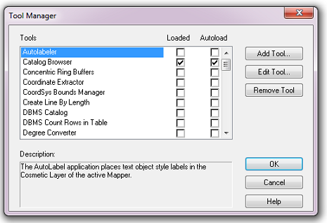
Fig. 4.5 The Tool Manager in MapInfo 12 or earlier
In the Tool Manager dialog, click Add Tool…, then locate the tool using the browse button … on the Add Tool dialog (Fig. 4.6). Enter a name in the Title box (e.g. ‘DataExtractor’), and a description if desired. Then click Ok to close the Add Tool dialog.

Fig. 4.6 Adding a tool in Tool Manager
The tool will now show in the Tool Manager dialog (Fig. 4.7) and the Loaded box will be checked. To load the tool automatically whenever MapInfo is started check the AutoLoad box. Then click Ok to close the Tool Manager dialog.
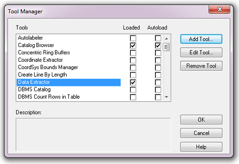
Fig. 4.7 The Data Extractor tool is loaded
The tool will now appear as a new entry in the Tools menu (Fig. 4.8).
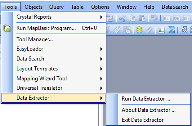
Fig. 4.8 The Data Extractor tool menu
Note
The name that will appear in the Tools menu is dependent on the ToolTitle value in the configuration file, not the name given when adding the tool using the Tool Manager.
Tip
It is recommended that a MapInfo Workspace is created that contains all the required GIS layers to run the tool. Once this workspace has been set up and the tool has been configured and installed, running the Data Extractor tool becomes a simple process.
4.3.2. Installing the tool in ArcGIS
Installing the tool in ArcGIS is straightforward. There are a few different ways it can be installed:
4.3.2.1. Installation through Windows Explorer
Open Windows Explorer and double-click on the ESRI Add-in file for the Data Extractor tool (Fig. 4.9).

Fig. 4.9 Installing the Data Extractor tool from Windows Explorer
Installation will begin after confirming you wish to install the tool on the dialog that appears (Fig. 4.10).
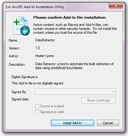
Fig. 4.10 Installation begins after clicking ‘Install Add-in’
Once it is installed, it will become available to add to the ArcGIS interface as a button (see Customising toolbars).
Note
In order for this process to work all running ArcMap sessions must be closed. The tool will not install or install incorrectly if there are copies of ArcMap running.
4.3.2.2. Installation from within ArcMap
Firstly, open the Add-In Manager through the Customize menu (Fig. 4.11).
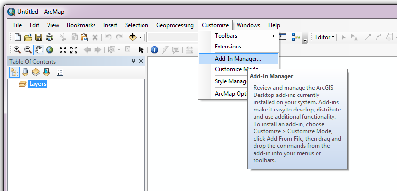
Fig. 4.11 Starting the ArcGIS Add-In Manager
If the Data Buffer tool is not shown, use the Options tab to add the folder where the tool is kept (Fig. 4.12). The security options should be set to the lowest setting as the tool is not digitally signed.

Fig. 4.12 The ‘Options’ tab in the ArcGIS Add-In Manager
Once the tool shows in the Add-In Manager (Fig. 4.13), it is available to add to the ArcGIS interface as a button (see Customising toolbars).

Fig. 4.13 The ArcGIS Add-In Manager showing the Data Extractor tool
4.3.2.3. Customising toolbars
In order to add the Data Buffer tool to the user interface, it needs to be added to a toolbar. It is recommended that this is done inside a document that has already been loaded with all the data layers that are required for the tool to run. The tool should then be saved with this document (see Fundamentals of Saving your Customizations for an explanation of how customisations are stored within ArcGIS).
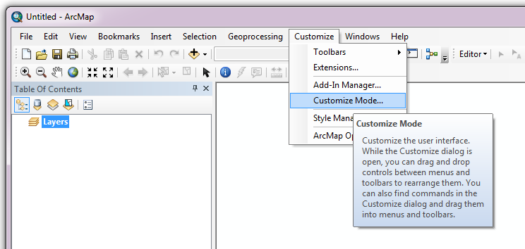
Fig. 4.14 Starting Customize Mode in ArcGIS
Customising toolbars is done through the Customize dialog, which can be started either through the Add-In Manager (by clicking Customize, see Fig. 4.13), or through choosing the ‘Customize Mode…’ option in the Customize Menu (Fig. 4.14).
Once this dialog is open, ensure that the check box ‘Create new toolbars and menus in the document’ is checked in the Options tab (Fig. 4.15).
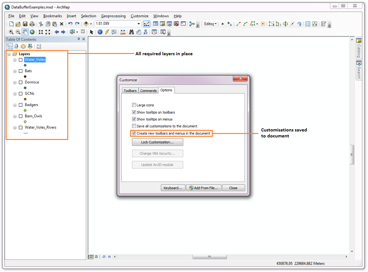
Fig. 4.15 Customising the document in ArcGIS
It is recommended that the button for the Data Extractor tool is added to a new toolbar. Toolbars are created through the Toolbars tab in the Customize dialog, as shown in figures Fig. 4.16 and Fig. 4.17.

Fig. 4.16 Adding a new toolbar in ArcGIS

Fig. 4.17 Naming the new toolbar in ArcGIS
Once a new toolbar is created and named, it is automatically added to the ArcMap interface as well as to the Customize dialog (Fig. 4.18. In this case the toolbar was named ‘TestToolbar’).

Fig. 4.18 New toolbar added to the ArcGIS Interface
As a final step the Data Extractor tool is added to the toolbar. This is done from the Command tab in the Customize dialog (Fig. 4.19). Click on Add-In Controls and the Data Extractor tool will be shown in the right-hand panel.

Fig. 4.19 Finding the Data Extractor tool in the add-in commands
To add the tool to the toolbar, simply drag and drop it onto it (Fig. 4.20). Close the Customize dialog and save the document. The Data Extractor tool is now ready for its final configuration and first use.

Fig. 4.20 Adding the Data Extractor tool to the new toolbar
In order to function, the tool needs to know the location of the XML configuration file. The first time the tool is run, or whenever the configuration file is moved, a dialog will appear asking for the folder containing the XML file (Fig. 4.21). Navigate to the folder where the XML file is kept and click OK. If the XML file is present and its structure is correct, the Data Searches form will be shown. Even if the tool is not run at this time, the location of the configuration file will be stored for future use.
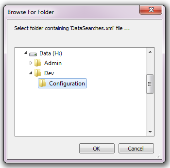
Fig. 4.21 Locating the configuration file folder